
Double Fixed Gate
Installation InstructionsGate Installation Instructions for Concrete Floors
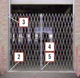
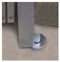
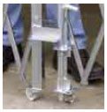
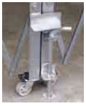
• Bottom of gate hinges on bearing washer and pin set into floor hole. Do not remove bottom floor pin.
• Top of gate hinges on “L” bracket bolted to wall or door frame.
• To install gates inside overhead doors, bollards or to clear obstructions, 6” or 9” extension brackets are required.
• Optional “H” Bracket joins each half of gate for added security.
Parts List:
Bearing Washers – Bottom hinges
2″ Standard “L” Brackets – Top Hinges

Gate Installation Instructions Graphic
Gate Installation Instructions – Steps
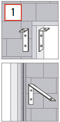 Before Installing decide on gate placement. “L” brackets that form top hinge allows gate placement in the recess of door frame. Installation can also be made outside or inside of wall next to door or opening frame. Either side of gate can be toward the outside
of building. Put the “operating side” (the end with center drop pins) to the side used when padlocking the gate halves. A label on the operating side indicates RHT (right) or LFT (left) of a person facing the operating side.
Extension brackets (order separately) clear overhead door tracks, bollards or obstructions. 6″ brackets provide 4-3/4″ clearance, 9″ brackets provide 7-1/4″ clearance.
 Have a helper extend the gate and stand it upright where it will be mounted.
CAUTION: Check to confirm gate will swing away from opening when not in use. This will provide a clear opening for normal traffic.
- Drill 3/4″ diameter x 3″ deep hole, 1-1/4″ from wall into the floor for gate pin to set into.
- For 6″ extension bracket drill 6″ O.C. from wall.
- For 9″ extension bracket drill 9″ O.C. from wall.
Place a bearing washer over floor hole and set bottom gate pin into floor mount hole.
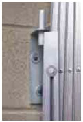 Extend gate and hang “L” bracket on top of gate to verify where it will be mounted. To release tension you may lift the wheel 1/2”-3/4” off the floor. Mark and drill pilot holes into door frame or wall. It may be easier to drill pilot holes if you remove the gate from it’s floor mount. Place bearing washer and bottom gate pin back into floor mount. Slip “L” bracket over top of gate and bolt (bolts not included.)
- Wood door frames or walls: 5/16” x 2” lag bolts.
- Steel door frames or walls: Drill and tap for 5/16” x 2” lag bolts.
- Brick or concrete frames or walls: 5/16” x 2” lag bolts set into 3/8” holes with lead anchors.
 Raise center drop pin and use attached notch to keep in place, this prevents damage to floor surface. Extend and retract gate to its stops to work out stiffness. Repeat steps 2-3 for other half of gate. CAUTION: Notice that center drop pin at this stage hits the other half of gate or rests on floor. Do not cut off drop pin. Step 5 addresses misalignment.
 With center drop pin raised, extend both halves of gates together to center of opening, mark floor for center drop pin hole and drill a 3/4″ diameter x 3″ deep hole. Lower center drop pin (Note: some larger gates have an additional pin in the center of each web, mark and drill these last.) Secure gate halves with 1/2″ shaft diameter padlock. Open gates slowly at first to avoid warping
- Keep fingers out of web pinch points.
- Do not set gate on its wheel, gate will run away and fall.
Blockader Gates is a division of the Tamis Corporation.